PROPOLOGY
Tabletop Scanning Electron Microscope
"Rabehl Scientific TT-1B" from the TV series ARROW
Project Breakdown
Richard Molnar:
I'd loosely based the design of this prop on reference photos of tabletop SEMs made by Hitachi and Nikon:
I'd loosely based the design of this prop on reference photos of tabletop SEMs made by Hitachi and Nikon:
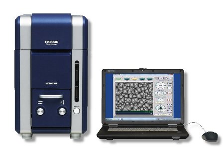
Hitachi TM3000
|
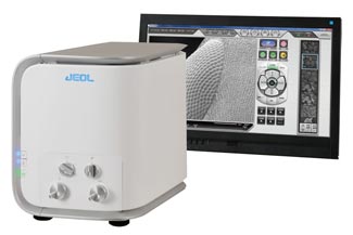
JEOL (Nikon) JCM-6000 NeoScope Benchtop SEM
|
Two different housings were submitted for consideration (see below). The one selected was my favourite. It was kind of a mash-up between the colour and design cues of the Nikon SEM, with the general proportions and layout of the Hitachi version (both were stock computer cases I'd sourced).
Before being approved however, a number of crude mockups were thrown together and photographed for Production approval. The version finally selected, was the least elaborate of those submitted.
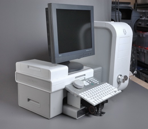
This was the most elaborate configuration submitted. It proposed that the SEM would be connected to a purpose-built computer/monitor/printer.
|
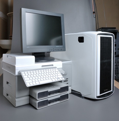
This version featured the alternate housing choice for the SEM.
|
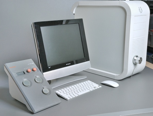
The chosen configuration. (Note the single aluminium dial… the only one on hand at the time).
|
Control Panel Mockup
|
There were 9 different versions submitted for Production approval (click photos to enlarge). All included an LCD monitor, keyboard, and mouse that were ultimately supplied by Production (different from those used in the mockups).
|
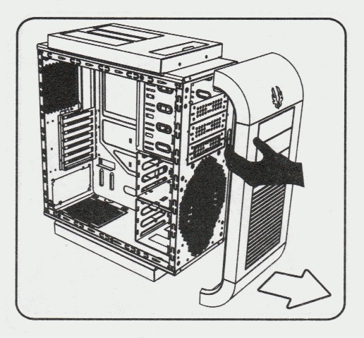
Once the chosen case was selected, I needed to relocate the drive bays from the top, to the bottom, in order to accommodate the planned location of the specimen chamber drawer. This was achieved by first drilling out the rivets that held the front chassis together, inverting it, then re-riviting it back together (I also removed a hard drive cage that was going to be problematic). It was then a simple matter, to snap the case fascia back on… inverted 180 degrees.
|
|
|
Prior to modifying the computer case, I'd dropped off a 1:1 rendering of the control panel and some decal designs to a favourite sign shop of mine for output.
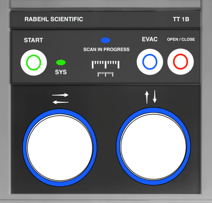
They produced 2 control panel cosmetic pieces made from a novel clear/colored layered plastic sheet (as well as some custom decals). When "reverse engraved" this material provides the option of backfilling the engraved features with paint in the color of your choice (making it appear custom printed), or leave it transparent for backlighting. I used both options. The finished control panel that looks as though it had been reverse silk-screened on polycarbonate sheet, and is indistinguishable from a commercial, mass-produced product. 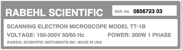
Product Nameplate
|
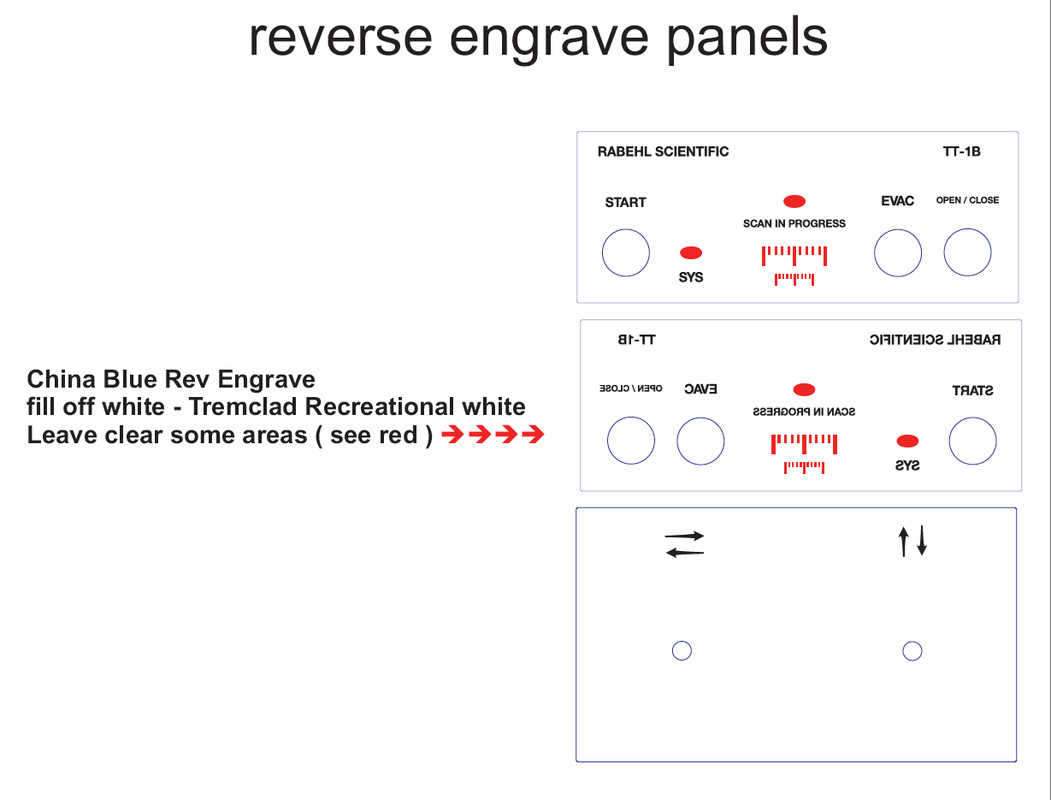
Control Panel Reverse Engraving

Warning Decal
|

The tabletop SEM on set.
|
Although I made an effort to stay true to the attributes possessed by real tabletop SEMs, one feature everyone wanted to see, was a motorized specimen chamber door. It was simply deemed more interesting than the manually operated version found on the genuine article.
To this end, Prop Master, Ken Hawryliw suggested that I consider using the tray mechanism from a CD/DVD drive in order to achieve this effect economically. Unfortunately, this kind of mechanism is only suited to transporting disk media, and was quickly abandoned in favour of a purpose-built mechanism. Other concessions made to enhance the appearance, were the inclusion of LED lighting inside the specimen chamber, and a "blue-halo" effect that radiates from the aluminium "X/Y" control dials. |
Another "enhancement' suggested by the design, was the purported ability to position the specimen stage via electric motors controlled by the X/Y dials. This concept was really born out of necessity. Real SEMs actually had elaborate and precise mechanical linkages connected to the X/Y dials that were fully visible whenever the specimen chamber door was open. Given time and budget constraints, I opted for suggesting that this particular SEM had an advanced "position-by-wire" feature, which justified the simplified design of the positioning mechanism.
|
Another imagined "advanced feature" was the "COURSE and "FINE" X/Y adjustment. This novel feature was simulated by pressed the face of either positioning dial, which caused backlit indicators to toggle between large and small scales. This feature was relatively easy to achieve, given that the dials were actually a ready-made computer accessory that already incorporated an internal momentary switch (as well as the aforementioned "blue-halo" illumination).
|
|
|
Choosing this particular item to serve as X/Y dials, was inspired by something I noticed in one of the EM reference photos I'd gathered:
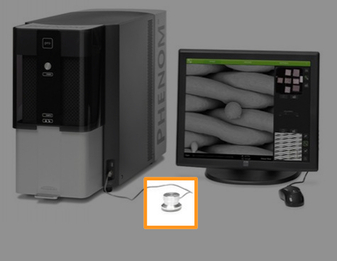
The highlighted item is a GRIFFIN TECHNOLOGY "Powermate".
It immediately caught my eye, as it was something I use everyday… an accessory connected to my iMac called "Powermate".
|
EUREKA! I now had viable candidate for the requisite turned aluminium dials, with the added bonus, of a nifty lighting-effect, and a useful momentary pushbutton!
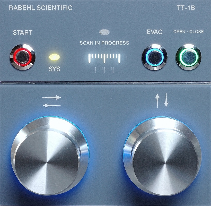
The Control Panel.
|
The electronics were a pretty straight forward amalgamation of off-the-shelf electronic modules for servomotor and LED indicator control. I choose this route, as it was faster, and more efficient (and less expensive to the client) to utilize on-hand solutions, rather than designing and building a custom control board:
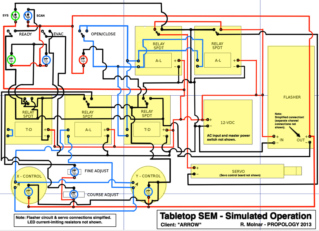
Control Electronics Schematic
Sometimes having a "good eye" and a little luck helps. The components that became the basis of the servo drawer assembly and specimen chamber base were made from 2 different sizes of stock, extruded aluminium, electronic enclosures that I sourced on the internet. Besides being the right size, they already had channels (intended for circuit boards) that could be used as a guideway for the movable drawer platform. The application of TEFLON tape to the edges that engaged the channels ensured smooth travel, and tightened up the tolerance to provide a more precise fit.
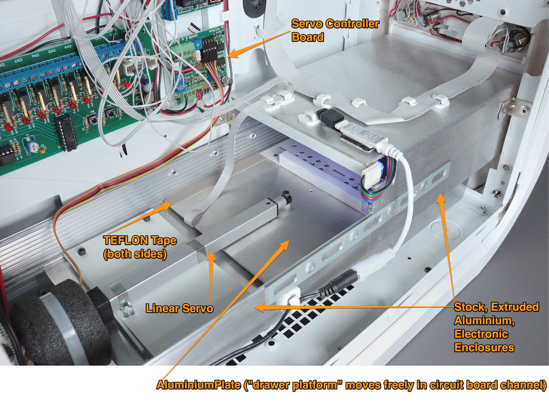
Internal Layout
When detailing props of this kind I aways make an effort to include some well thought out and interesting graphical treatment. To this end, I requested that Production "clear' a manufacture's name that I could incorporate into the front panel and nameplate. To my delight, they provided "Rabehl Scientific"; named after Ken Rabehl, a friend, and long-term colleague of mine.
It is common practice to use crew member names for this purpose, and at the time Ken was working as a member of the ARROW Art Department:
It is common practice to use crew member names for this purpose, and at the time Ken was working as a member of the ARROW Art Department:

Tabletop SEM - ARROW from PROPOLOGY on Vimeo.
Surprisingly little custom fabrication was required to complete this project. That said, a great deal of planning went into ordering the right components and ensuring that they would arrive on time in order to to meet the completion deadline. Really fun to design and build!
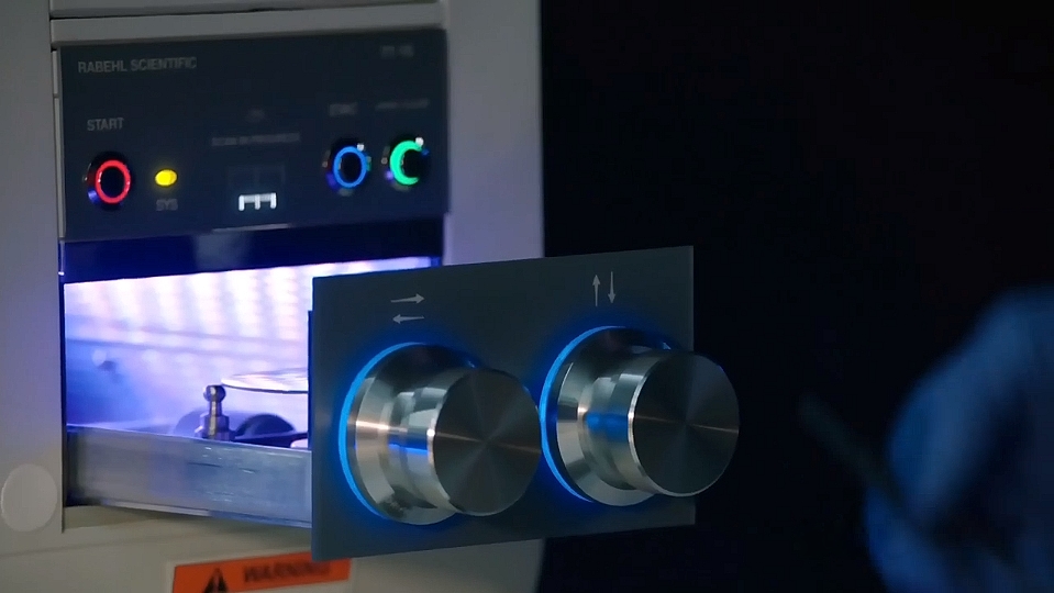
The RABELL SCIENTIFIC TT-1B tabletop SEM, as seen in the episode "The Scientist"