- Published on
Facial Obfuscation Processor with Computer Interface Device For the TV Series ARROW
- Author
-
-
- Name
- Posts
- Posts
-


A novel, advanced, microprocessor device with a companion interface unit.
Design Process
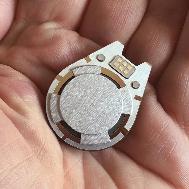
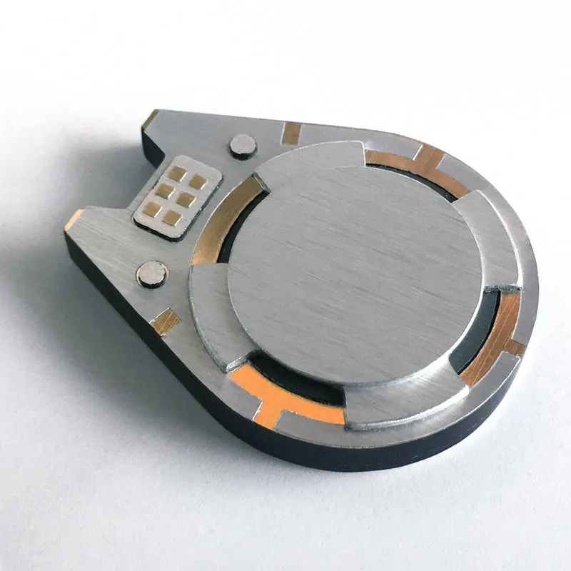
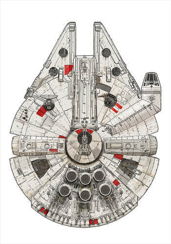
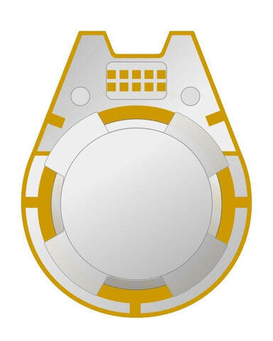
He suggested it be evocative of the Millennium Falcon from Star Wars. The characteristic notch feature of the Falcon's forward section was actually a useful attribute to duplicate. This could be adapted to our prop to serve as a "keyed connection" to the "Reader Interface" component.
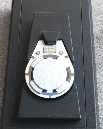
The finishes selected were brushed aluminum and polished gold. These were chosen to impart a sense of precious value, and to make the small processor easier to spot on camera.
Construction Process
Once the design had been approved, all requisite components were designed and rendered for output via CNC and laser cutting. These were made from either plastic or metal sheet-stock. In addition, cut-vinyl decorative features were designed and produced.
The two major assemblies ("processor & "reader interface") were built by layering the sheet-cut components atop one another, in proper order (like a layer cake). This was easily accomplished, as double-face adhesive sheet had been applied to certain components prior to being cut from sheet-stock. Most of the assembly procedure was merely a "peel & stick" process.
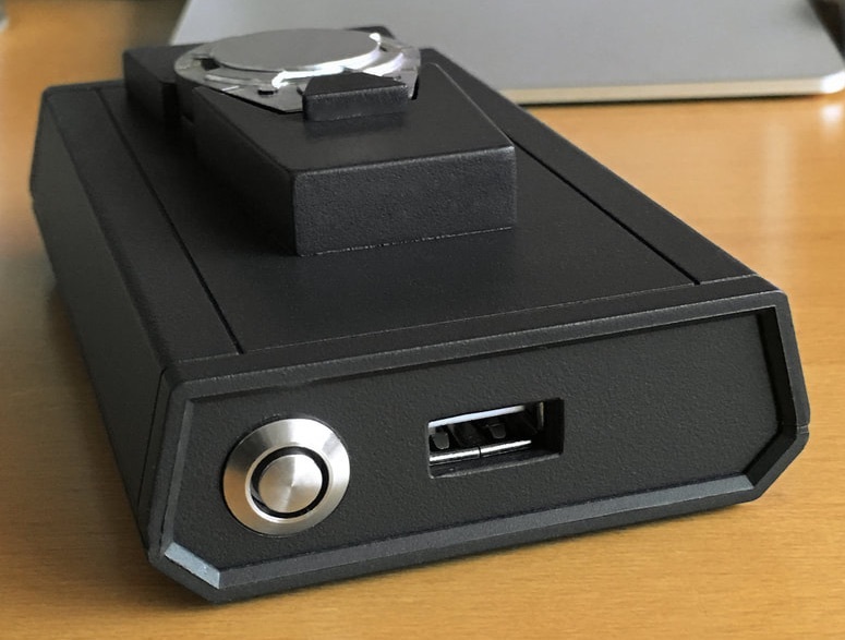
Sometime during construction, the Prop department expressed concern that the "reader interface" device might be too small visually, and perhaps awkward to use. The solution... an interesting off-the-shelf electronics enclosure was added to the original assembly to make it more visually substantive. Slate-gray paint was applied to both to provide uniform color and finish.
This change actually made it easier to incorporate the electronics required for the planned LED lighting effects. Originally, this was to be accomplished by installing the control electronics (less the LEDs installed into the processor itself) into a separate housing that was to be off-camera. This would contain the power supply and effects circuitry, and would have been attached to the reader by a cable connection. Now all the requisite components could be housed in a single on-camera device.

Operational Features
Given the diminutive size of the processor unit (1-1/4" x 1-1/2" x 1/8") it would be technically difficult to fit the electronics inside necessary to provide the desired lighting effect. A "cheat' was devised that allowed all of the electronics (including the LEDs) to be housed within the interface unit, instead of the processor itself.
Ostensively, when placed into the interface unit, the processor would become "active", "read and "write" operations would be indicated by flashing blue indicators visible on the processor. In reality however, this was accomplished by providing 4- 3mm "optical ports" to the underside of the processor unit. These would nestle over 4- 3mm blue LEDs installed into the reader socket (notionally, a kind of "digital-optical I/O device).
A small rare-earth magnet was also fitted to the centre of the processor assembly. This would cause a magnetic reed switch to close that was installed behind the socket whenever the processor was inserted and would trigger the lighting effects.
When the LEDs built into the reader became active, their light would be transmitted through the 4 clear ports around the processor's perimeter. This gave the impression that the processor contained functional electronics, while in fact, it was totally inert.
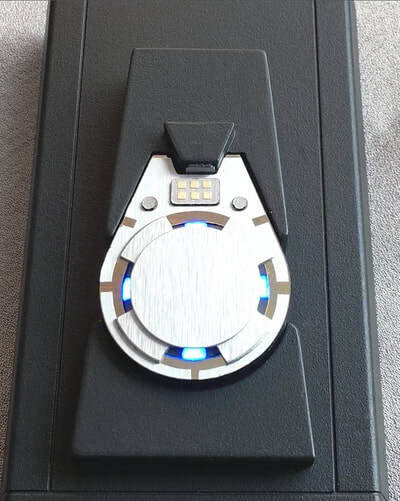
The sequential LED illumination control was provided by an off-the-shelf, 3-channel, RGB-LED controller. Only 2- channels were utilized, each being tied into 2-pairs of LEDs (Pair-1: north-south orientation-- pair-2: east-west orientation).
This controller features multiple flash modes/rates. This made it easy to find a pleasing combination of settings that conveyed the desired "read/write" visual effect.
Conveniently, these settings would be saved into non-volatile memory, and would remain unchanged, even if the power was interrupted.

Video Demonstration
A novel project, that presented an interesting technical challenge.