- Published on
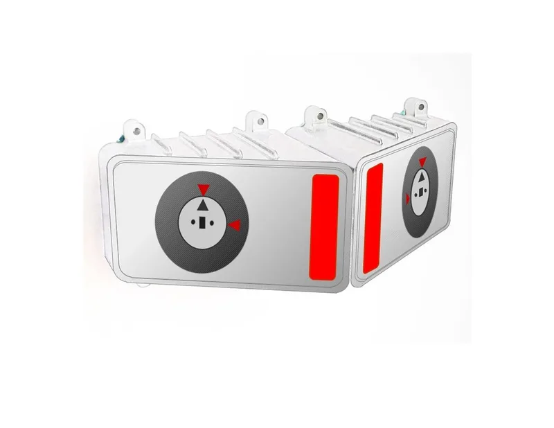
Dual-Keyed Interlock Device - For the TV Series ARROW
- Author
-
-
- Name
- Posts
- Posts
-

Since this was an important and fairly complex item to produce (especially on a tight schedule) the ARROW Prop Department wisely decided to split the work between two vendors... PROPOLOGY & IRL CREATIVE.
Design Process


Construction Process
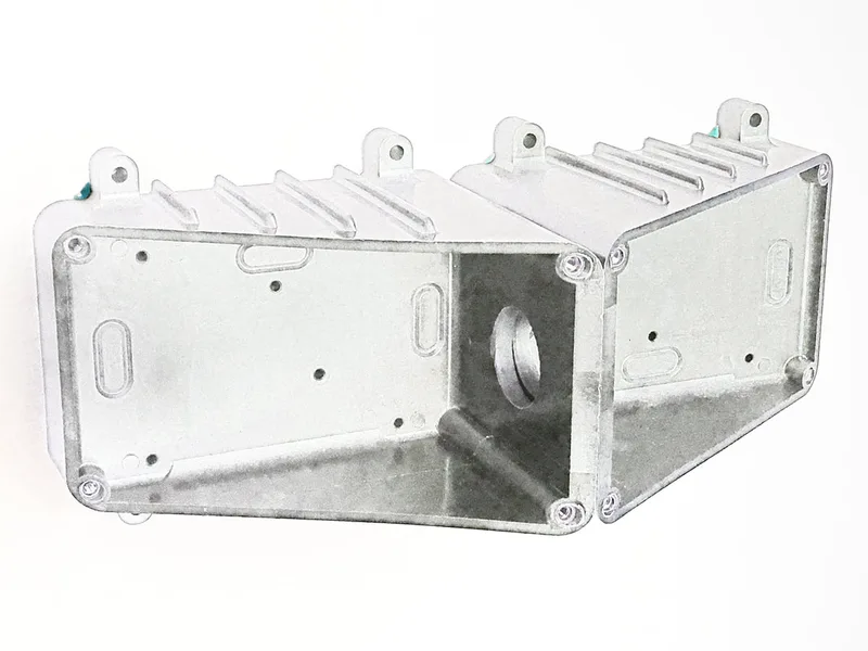
Fabricating the device housings was a fairly straight forward process. Each incorporated part of a uniquely styled electrical box that was already on hand from our shop stock and were made from a kind of phenolic-plastic. These had been obtained years ago from Boeing Surplus Sales in Washington state.
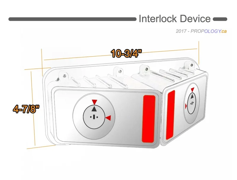
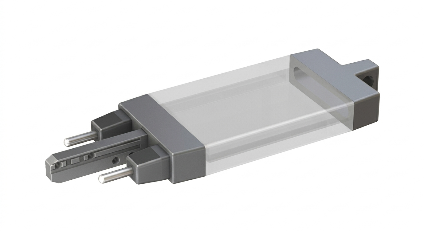
They were a two piece affair; each with a 45 degree slope on 2 of their joining faces. Aligned as intended, they would combine to create a rectangular shaped housing. For this project however, only the lower half of each would be used. Once our custom faceplates were installed, each housing would exhibit the sloped-front design that we desired.
These lower housings were mounted to the centre of a backing plate made from 1/4" acrylic plastic sheet, with the taller aspect of their sloped design facing each other. This was achieved with the use of the existing mounting flanges; each featuring a through-hole for a fastener. Holes were drilled and tapped into the backing plate corresponding with the location of these flanges. Eight stainless steel hex/cap screws were used to hold everything together.
Embedded Into the rear aspect of the backing plate were several rare-earth magnets. This was to furnish convenient and secure attachment to a certain scripted set-piece: a steel, marine shipping container.
Layered Assemblies
Meanwhile, IRL Creative was making the keys and key-way assemblies that would later be installed into each housing. At the same time, work progressed at PROPOLOGY to fabricate the front face plate assemblies for each.
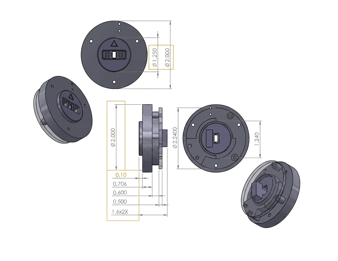
These consisted of several layers of plastic and metal sheet stock that had been cut via laser and CNC router. These cut parts would then be mounted together via double-face adhesive sheet to form a complete faceplate assembly. Each layer had certain cut-outs, that when fastened together in the correct order, would accommodate the requisite internal mechanical and electrical components.
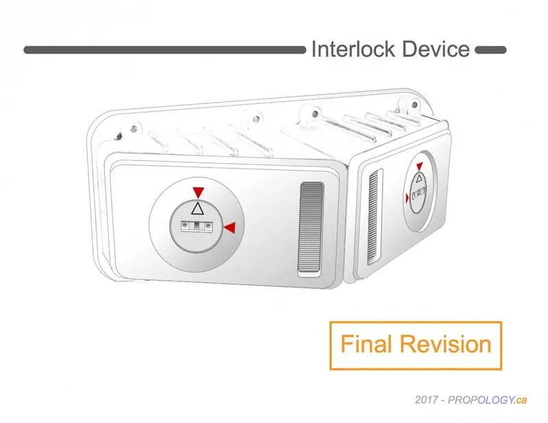
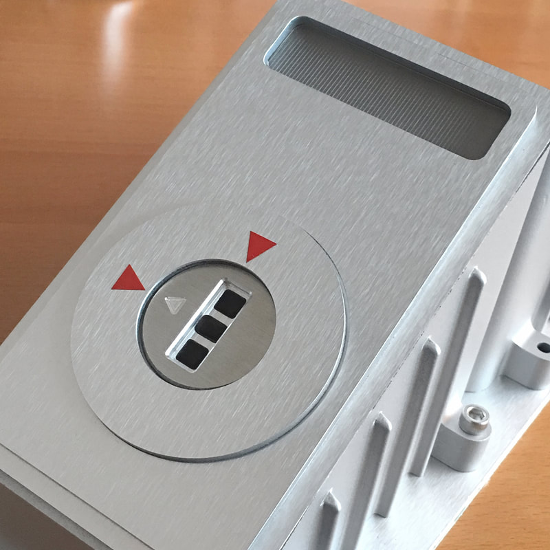
The top surface of both housing covers and the top of the backing plate were faced with clear-anodized, brushed-aluminum metal sheet. To complement this (and to suggest that the entire device housing was made from a metal casting) all other exposed surfaces were painted in a matte-aluminum finish. Together, this gave the impression that these housings were made from solid metal.
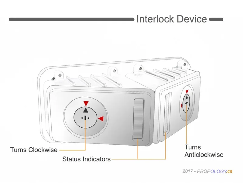
Illuminated LED Indicators
Each faceplate included a large and illuminated "status indicator" component that was composed of several cut plastic sheet parts that would combine to create a light-box incorporating a diffuser lens. The brushed aluminum top plate and plastic substrate of the faceplate assembly featured suitable openings that corresponded with the size/shape of the diffuser lens component.
Each lens was laser-cut from 1/16" clear acrylic sheet and featured thinly engraved parallel lines that horizontally traversed the narrow vertical aspect of the lens, spanning its entire height. This process, combined with the addition of self-adhesive "privacy-film affixed to the bottom of the lens, provided the necessary diffusion to the LEDs within the light-box.
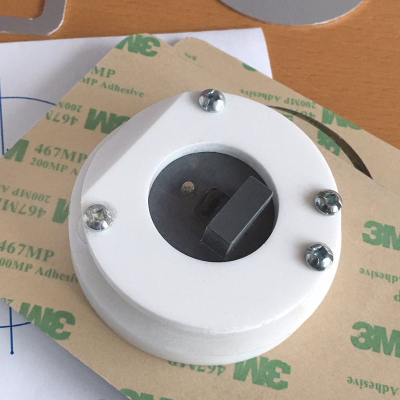
The light box component was made from white plastic sheet (Sintra). The white colored interior would contribute extra diffusion of the installed LED illumination by allowing the light it produced to bounce around the enclosed space before exiting through the diffuser lens.


Sequential LED Operation
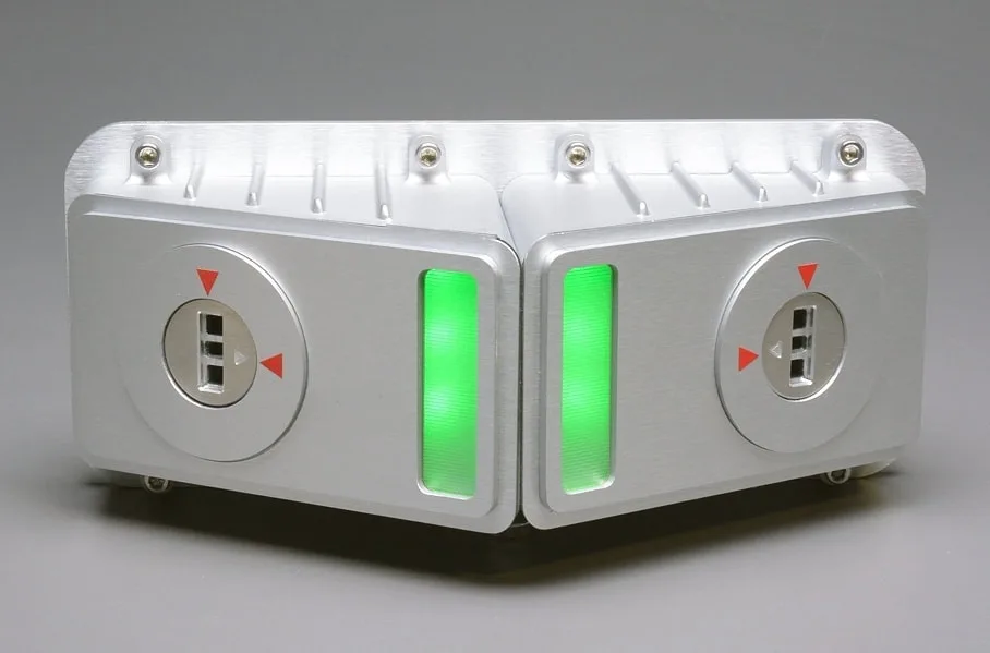
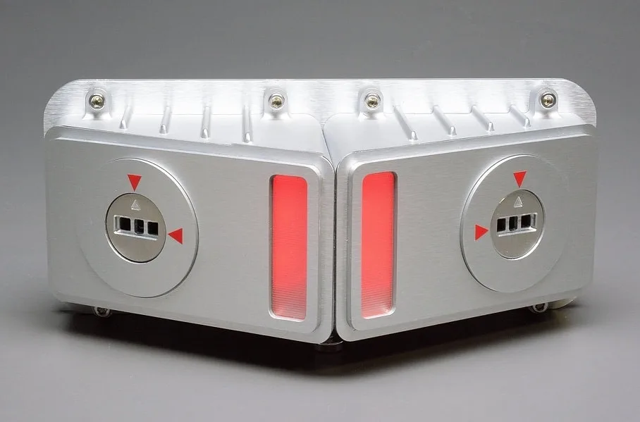
The requisite electronics consisted a simple circuit that would cause the LED status indicators to illuminate, red-to-green. The onboard power was supplied via 9-volt batteries.
The LEDs chosen, were short RGB strips. This type of LED would provide the requisite wide-angle illumination required to adequately flood each indicator window (only the red and green channels were utilized).
The desired sequencing of the LED indicators was provided by microswitches that were installed into each keyway assembly (2- per unit).
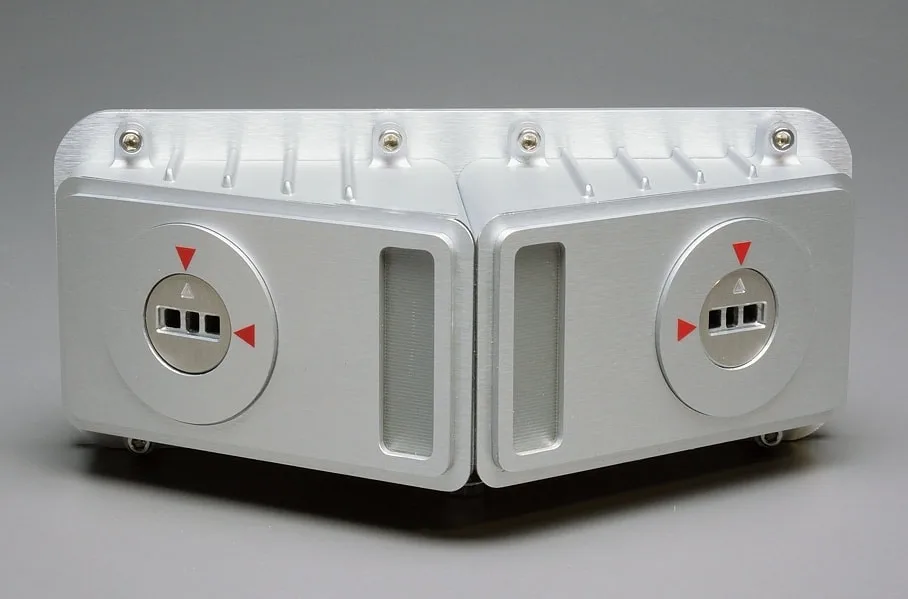
One switch was situated at the far end of the key-way that would close whenever a key was inserted. This would cause the red LED indicators to illuminate, signifying: "KEY PRESENCE VERIFIED".
The second microswitch was positioned in the path of a cam. Whenever the key-way was rotated 45 degrees, the cam would actuate the switch, and the red indicators would change to green, signifying: "UNLOCK GRANTED".