- Published on
Detailing the "Quantum Processor" For the TV Series ARROW (with UNLIMITED DESIGN)
- Author
-
-
- Name
- Posts
- Posts
-

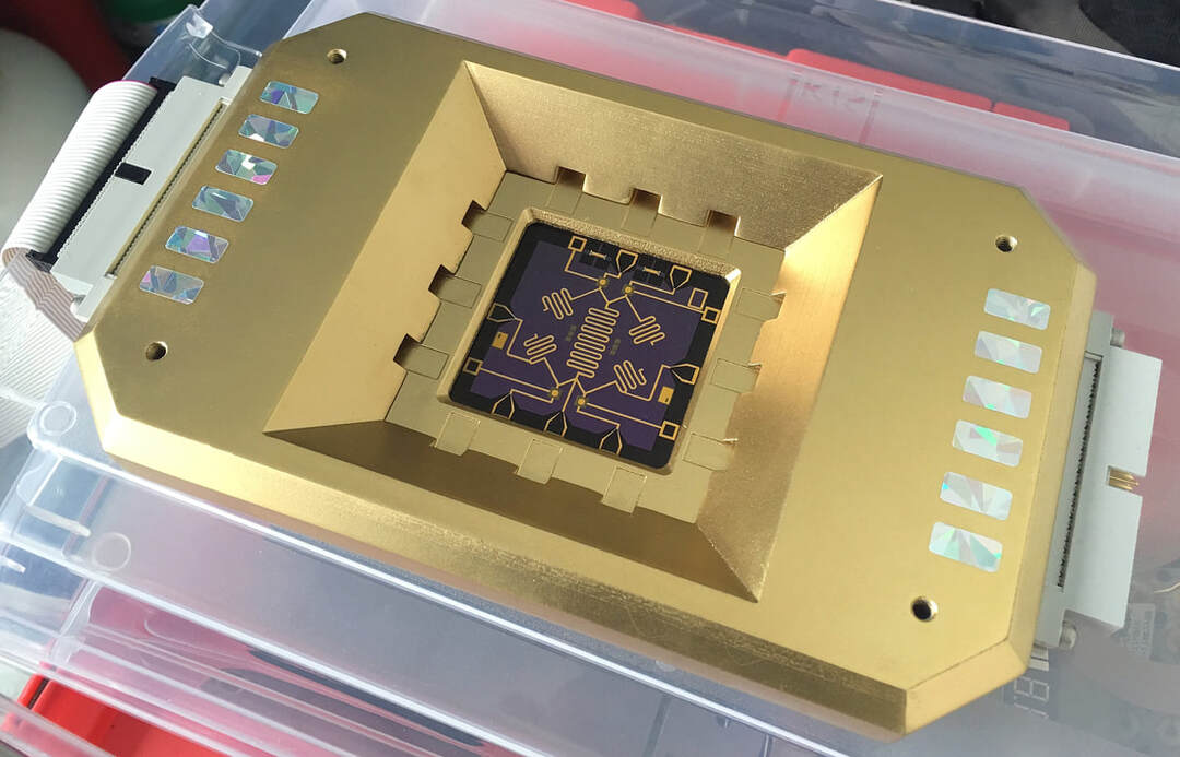

This prop was detailed by PROPOLOGY prior to its completion by UNLIMITED DESIGN.
This project was co-produced by UNLIMITED DESIGN LTD and PROPOLOGY. Due to logistics and time constraints, the design and construction activities were shared by both companies at the request of the ARROW Prop Department.
Background
The elements that PROPOLOGY contributed to this project (as seen above):
In total, 4 units were detailed-- 2-each-- with 2 different chip styles
- Attachment of IDE hard drive connectors (x2 pair).
- Male to male IDE ribbon cables (x2 pair).
- Metallic/iridescent cut-vinyl detailing.
- Design, manufacture, and installation of simulated silicone wafers
In total, 4 units were detailed-- 2-each-- with 2 different chip styles
Design Reference
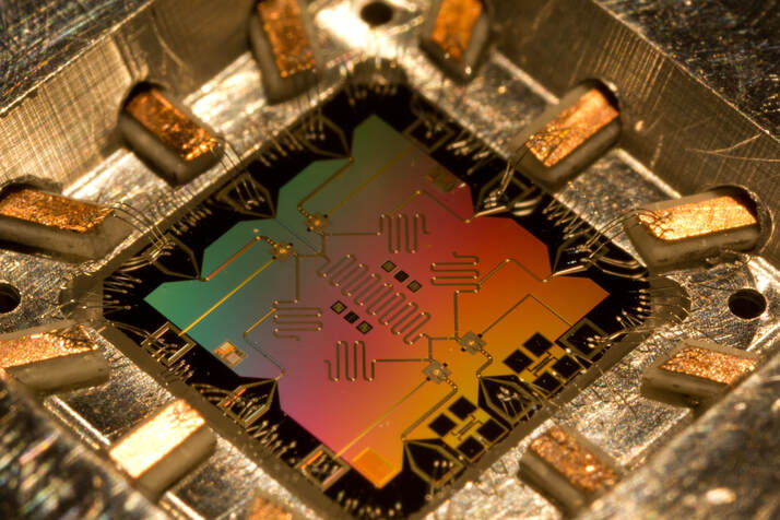
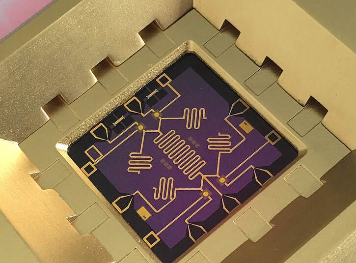
The design of the silicone chip was based upon a reference image provided by the ARROW Prop Department.
The Image below depicts a real experimental quantum computer processor. It is physically quite tiny. In fact, the thin gold wires in evidence are much thinner than a human hair.
The Image below depicts a real experimental quantum computer processor. It is physically quite tiny. In fact, the thin gold wires in evidence are much thinner than a human hair.

Design Reference
Design Process
It was decided by Production that the ARROW version would be substantially scaled-up for dramatic and practical reasons. The larger size made it seem more impressive and was far more "camera-friendly".
The main challenge for PROPOLOGY was to provide a silicone wafer component that was evocative of the real thing, while integrating convincingly into the unit that had already been fabricated. In addition, a second similar design was required that would depict a so-called "reverse-engineered" version. Shown below are the approved processor designs.
The main challenge for PROPOLOGY was to provide a silicone wafer component that was evocative of the real thing, while integrating convincingly into the unit that had already been fabricated. In addition, a second similar design was required that would depict a so-called "reverse-engineered" version. Shown below are the approved processor designs.

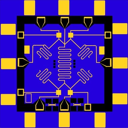
"Original" Version
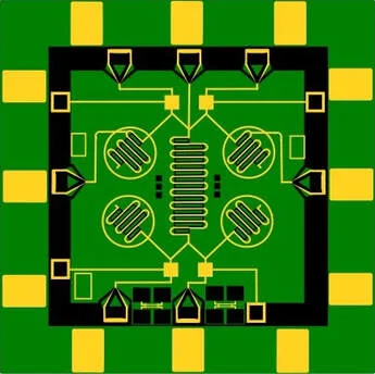
"Reverse Engineered" Version
Construction Process
The multicolor circuit elements were rendered via gold and black foil transfers onto self-adhesive vinyl. This method rendered the gold "circuit-traces" in a color and lustre similar to that of the painted main body.
The "original version" required some ingenuity to produce. The color foil transfer process we were using normally utilized self-adhesive vinyl stock in perf-edged rolls. That said, to achieve the desired look for the chip-substrate, an automotive type self-adhesive vinyl was chosen which unfortunately was not available in perf-edged rolls. This meant that this vinyl had to be carefully transferred to some discarded perf-edged release paper before it could be printed upon. Once accomplished however, the transfer process proceeded with little difficulty.
The extra effort incurred to utilize the specialty vinyl was worth it, as it had a dynamic color changing quality, that was evocative of real silicone wafer substrate.

Prismatic cut-vinyl detailing was also added to the main body to add some eye-catching highlights.
Additionally, IDE hard drive connectors were mounted at either end of the main housing. These connectors were required to accommodate an on-screen action showing the processor being connected to another device.
Once detailing was completed, the processors were sent back to UNLIMITED DESIGN for final assembly.
PROPOLOGY is often asked to contribute to multi-vendor projects and welcomes these collaborations.
0 Comments