- Published on
Subway Electrical Boxes - From the TV Series ARROW
- Author
-
-
- Name
- Posts
- Posts
-

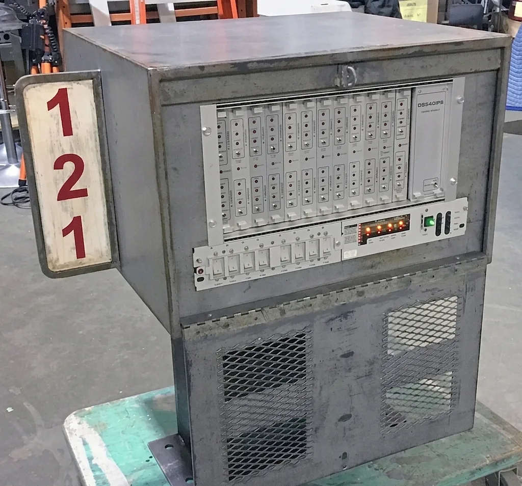
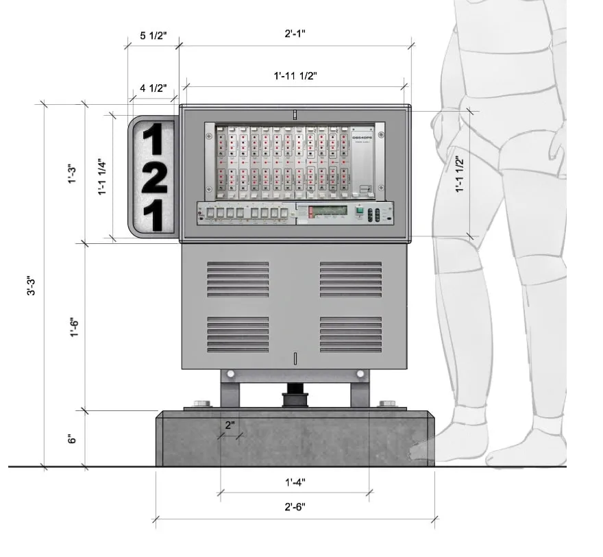
Subway Control Electronics Box

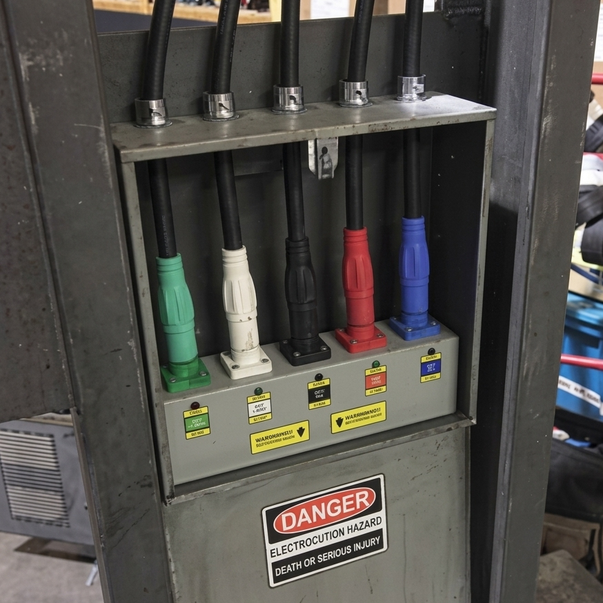
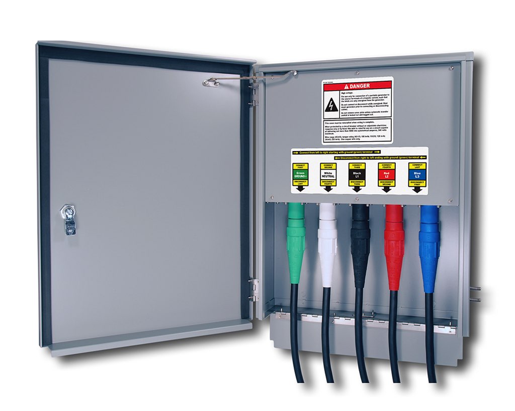
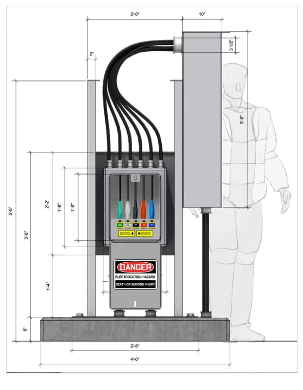
Subway Electrical Box
An ongoing challenge on ARROW: how to portray something that's inherently unrealistic in a way that is both plausible and interesting—in this case, how to depict someone disconnecting large gauge wires by pulling them out of a high-voltage electrical box... BY HAND... a task that would normally require special insulated tools... and way too much screen time.

Design Process
Thankfully, the answer was close at hand, as the solution was to use the same kind of electrical connections commonly used to furnish power to film locations. Unlike typical electrical box connections that are semi-permanent (and require tools to modify) the film industry uses specialized temporary connections that can be rapidly changed by hand.
The design reference below depicts the connector type known as a "Cam-Lock". Utilizing these, each cable could be disconnected with a simple anti-clockwise twist that disengages the plug
from the socket.

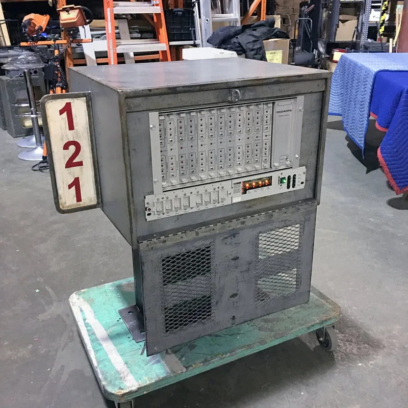
The other electrical box needed to depict some kind of plausible electronics that possessed removable circuit cards... a feature essential for the kind of shot the Director wished to achieve. The device chosen, was obtained from PROPOLOGY rental inventory (below).
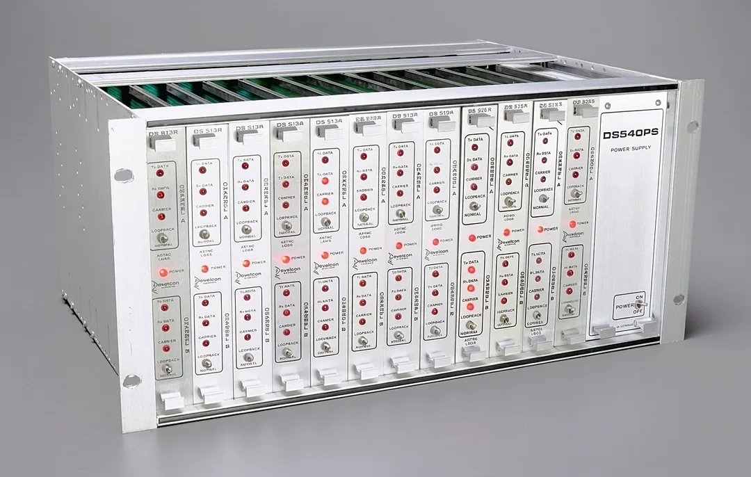
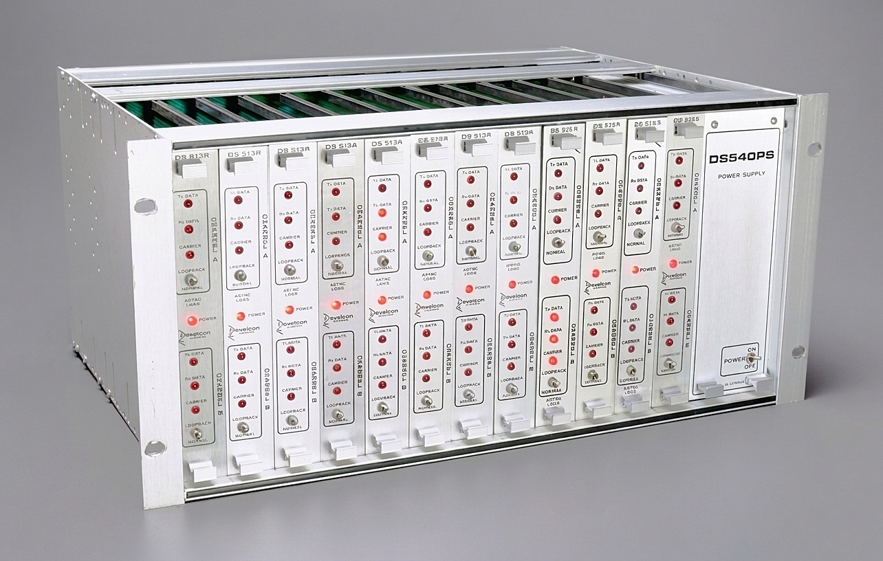
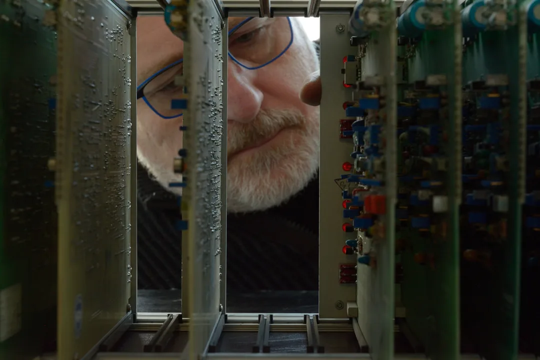
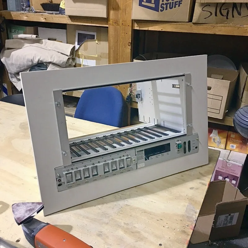
To ensure that the device would be suitable, a test-shot was provided to Production that depicted the view through the empty card slots (below).

Construction Process
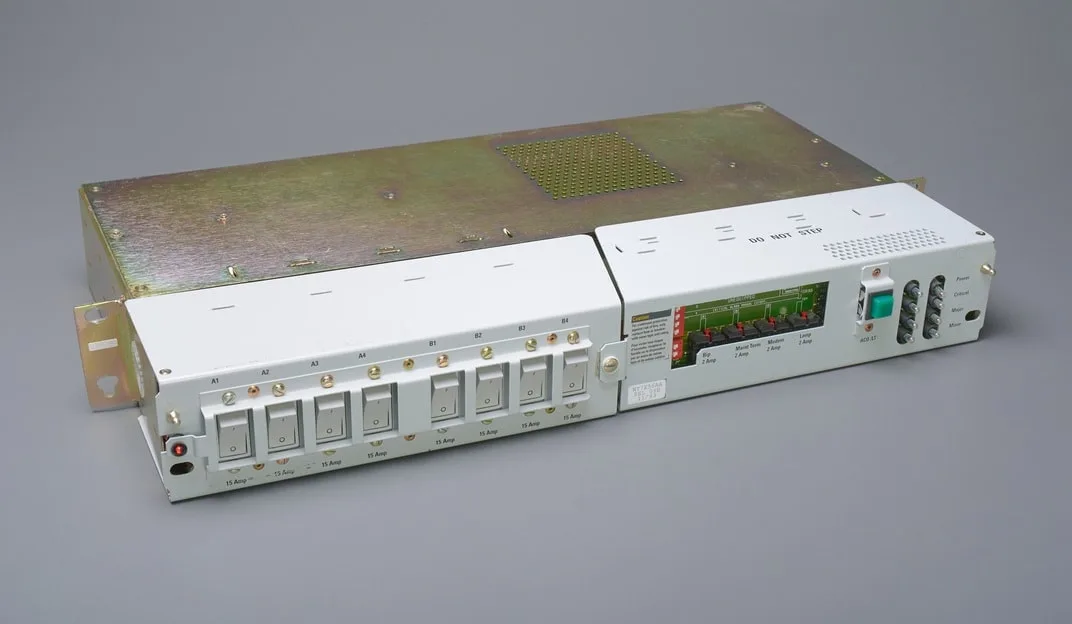
This was certainly one of those assignments where the design and approval process was far more involved than the actual build. The data switch component for the smaller electrical box had already been modified as required (during the mockup process) so it was pretty much ready to go.
The breaker panel component required some minor electrical work to provide some operational LED indicators, but other than that, it too was ready.
All that was needed now, was fabrication of a bezel that would suit both components and installation into the ARROW Construction Department provided set-piece. This was quickly accomplished and dispatched to the ARROW Paint Department for aging treatments.
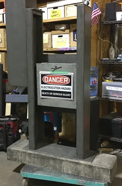
The larger set-piece was not complicated, and therefore, easier to complete... although it did require a good deal of attention during the design approval process. This was due to the concern that a non-technician may have difficulty smoothly disconnecting the cam-lock connections.
The solution: the use panel mounted female receptacles that weren't actually the type normally paired with the particular male connectors we were using.
Nearly complete (interior has not yet been aged).
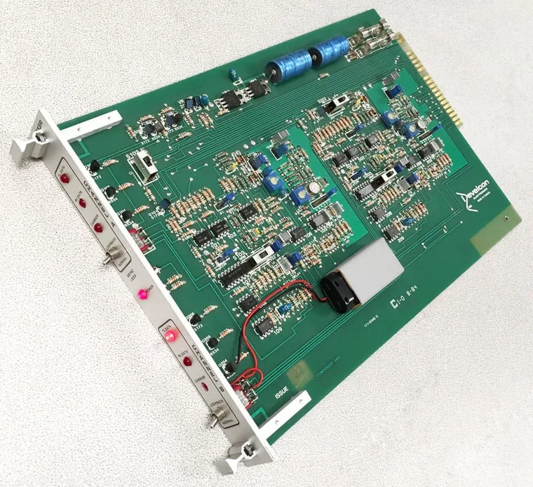
A circuit card rigged for the LEDs to illuminate.

Completed circuit card/breaker box
Test fitting a decal before application and aging.
Superficially, the two seem to mate properly, but without engagement of a locking mechanism. This made for a convincing, but easily achievable disconnection action.
Once approved, all that was required was to fasten the female connectors to the stock enclosure that had been sourced and apply custom decals...and off to the Paint Department for "aging".
By the greatest of luck, this enclosure was not only exactly the right size and proportions... it was even pre-painted in the correct color. As they say... sometimes, you just get lucky!